

Abstract
FAST Engineering has recently re-engineered an IEC 61850 Station Bus Substation Automation System, with multivendor IED’s using the top down engineering approach to system specification and integration. This was a proof of concept put forward to a utility to replicate an already in service design. The following is an outline of the process of engineering CID files through HELINKS System Tool Set comparable to the utility’s commissioned CID files created using multiple Vendor Tools.
Introduction
The utility owns, develops, operates and maintains a high-voltage electricity transmission network. After their decision to move to IEC 61850, the utility spent years researching and developing standards to implement the new technology. Recently their first IEC 61850 Station Bus Substation Automation System was commissioned and placed in service.
The IEC 61850 Protection Engineering Guide developed by the utility covered the process required to correctly configure the IEC 61850 component of a protection IED to nominated standards using a "bottom up" engineering approach to system integration. (Bottom up meaning starting with designing an IED, get it working and then move onto the next. One of the main benefits of this approach, especially with a new technology, is a more rapid understanding is developed of an operational system and the finer points affecting overall performance. One of the main negatives of this approach is that the engineering process is not easily modifiable or repeatable and design changes incur significant re-engineering) This included configuring the IED’s identity on the network, IED dataset names, GOOSE message publishing / subscribing and MMS interfaces for alarms, indication, analogues and control functions.
This article does not explain basic IEC 61850 concepts like Logical Nodes, GOOSE messaging or Reporting. Basic knowledge of IEC 61850 is helpful but not required to understand the power behind using HELINKS System Tool Set (HELINKS STS), a Vendor independent System Specification and System Integration tool. For some basic knowledge of IEC 61850 see the "What is IEC 61850" article. The purpose of this experiment was: to build comparable CID files using a "top down" engineering approach to system specification and integration without using the vendor tools for any engineering changes. Please read "Top Down vs Bottom Up Engineering" article for the benifits that can be gained from either Top Down Engineering or Bottom Up Engineering.
The IEC 61850 Bottom Up Engineering Approach
When using multiple vendors on a network all IED’s on the network require the GOOSE Datasets to be fully configured as well as GOOSE transmit / GOOSE send parameters to be fully configured before attempting any GOOSE subscribing / GOOSE receive mapping. This involves an incredible amount of back and forth between Vendor specific tools during design, maintenance or replacement projects.
- Starting with practical application of the project
- Starts with the problem you are trying to solve
- Informal learning environment (practical problem solving)
- Design changes require significant re-engineering
- Big Picture isn’t available until the end of design
- Inefficient for repeat work of similar designs
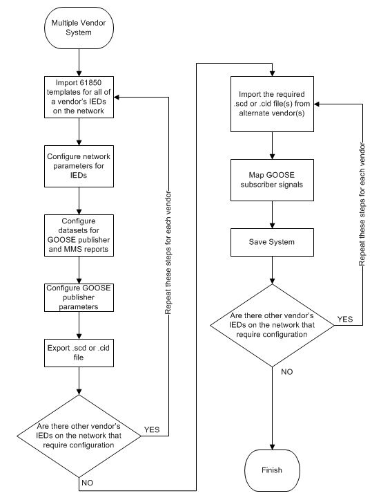
Fig. 1 Bottom Up Engineering Flow
What is HELINKS STS?
Based in Switzerland, HELINKS STS software is a manufacturer independent system tool set for IEC 61850. The software is used as a System Specification Tool and System Integration Tool as specified by section IEC 61850-7 of the standard. It does not remove the requirement for the Vendor Specific Tools also specified in this section. The Vendor Tools are still used to generate the final CID files and complete any IED specific settings outside the standard. The software offers a library driven, standards based engineering design process approach to system specification and integration. HELINKS STS has the ability for bottom up engineering and top down engineering, only using the vendor software with no further modifications required to build the final CID files for installation.
- Bottom up engineering, starts implementation with IEDs
- Top down engineering, uses a formal specification process
- Maintenance to fix bugs and make minor enhancements
- Replace parts or entire system
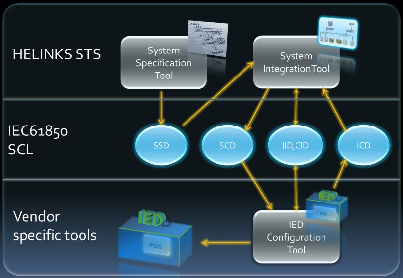
Fig. 2 Tool Interaction
- Graphically construct the Single Line Diagram (SLD) specifying voltages, bay types, primary plant components, bay names and layout. As the bay types and primary plant are drawn from library templates, any modifications to the underlying template affects all bays utilising the template.
- SSD can then be exported from the drawn Single Line Diagram in the resulting SCD file.
- Create hierarchical function blocks at each substation, voltage or bay level. These functions are a description functionally of what you want to happen eg. CB Fail Protection, CB Management, etc
- HELINKS STS can then be used to add expected Logical Nodes (LN) and resulting signals to each function block.
- Import capabilities via Excel provide a mechanism for creating libraries of virtual IEDs and the required LNs/Signals for each functional block.
- Specify Distributed communications via GOOSE for relevant protection function blocks and their interactions.
- Specification results in creation of SSD and SCD Files, LN and Signal Lists and Design Documentation.
- Import ICD files for the various required IED models.
- Instantiate virtual IEDs defined by the functional specification into real IEDs. This is where the magic happens and HELINKS maps LNs defined by the library based functional specification to the ICD LNs.
- HELINKS STS automatically derives Report and GOOSE configurations from the library based specifications. These can then be manually fine-tuned within the Communication Editor.
- Excel Signals List are then able to exported for the system updated for point to point testing.
- System Configuration Description History.
- General Specification
- Single Line and Functions
- Application Schemes
- Voltage Levels
- Transformers
- Data Attribute Glossary
- System Communication Diagram
- Subnetting/System segmentation
- IED Overview
- IED Summary
- Communication
- Reports
- GOOSE Messages
System Specification
The goal of system specification is to design a substation based on the voltage, bay layout and functional description of what you want. It is not intending to specify how this is completed or what IEDs are being used. For further details on why this step is so important for reducing engineering and whole of life costs see "What is IEC 61850 System Specification"
System Integration
Once system specification was completed then the system integration could be completed. For further description of the considerations in this step see "What is IEC 61850 System Integration". This is an iterative design approach and includes the following:
Documentation
Design documentation can be auto generated at any stage of the project for an "As Built" record of the design.
IEC 61850 Top Down Engineering Approach using HELINKS STS
Configuring HELINKS STS
Starting off in HELINKS STS, the first step was to create the Single Line Diagram using the System Specification Tool. After creating the Single Line Diagram of the substation template Bay Types were able to be extracted into a Function Library for further reuse. The LNs and signals required for each bay template type design had already been developed by the utility- these were able to be "massaged" into a format importable into the Function Library also. Once imported into the Function Library, these functions were then available for use in the graphical editor for the Single Line Diagram and Function Specification Diagram.
System Specification
The System Specification Description is started using the Single Line Diagram Editor. The true SCD hierarchy starts with the Substation Level and contains Voltage Levels. Bays are children of a Voltage Level. Bays can be duplicated with the associated Function Diagram. The first bay of each template type was created.
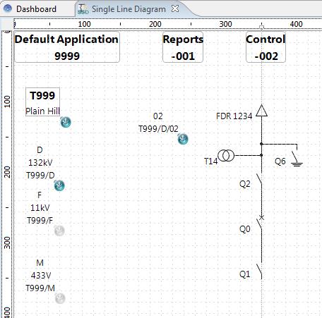
Fig. 3 Single Line Diagram, Example of a Bay
The Function Diagram Editor is used to complete the SSD file with Logical Nodes. Switching over to the Function Diagram Editor will show the signals associated with each device per bay configured from the Function Library.
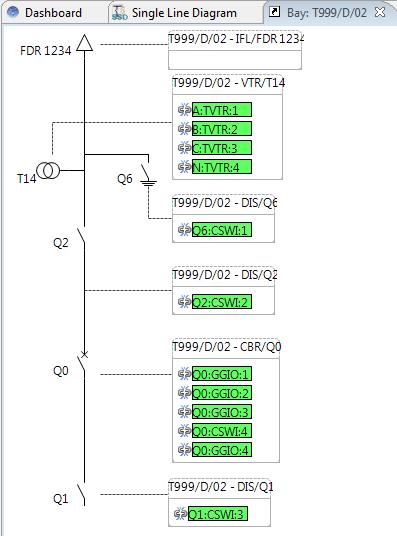
Fig. 4 Function Diagram, Example of Bay Creation
Virtual IED’s can now be added in the Function Diagram Editor followed by mapping the required protection functions required from the Function Library. The signals associated with each logical node can be defined if the design doesn’t follow the Function Library.
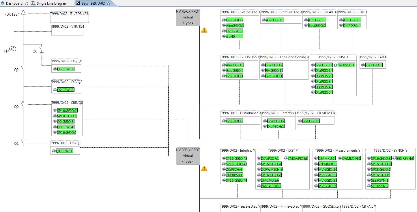
Fig. 5 Function Diagram, Example of Bay Creation with IEDs
Back in the Single Line Diagram Editor the bay can be "Copy/Pasted" for duplication, this will also duplicate the IEDs and protection functions associated with the bay being duplicated. Complete the Single Line Diagram and the Substation Specification Description is complete.
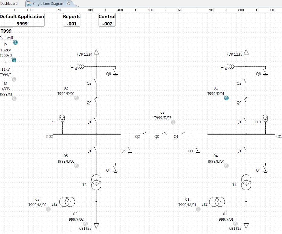
Fig. 6 Single Line Diagram, Example of Complete Single Line Diagram
HELINKS STS can export the System Specification Diagram .ssd file. By selecting the canvas in the Single Line Diagram all defined signals are shown in the Signals View. Selecting a bay, device or function will show the defined signals. HELINKS STS can export the signals shown in the Signals View to Excel.
System Integration
Before building the System Diagram, the ICD files for each type of IED to be used in the design should be imported into HELINKS STS. Using the System Diagram a SubNet can be created with switches, virtual gateways and connections added from the palette. Instantiate IEDs from the ICD tray and instantiate Gateways.

Fig. 7 System Diagram, Example of Bay Creation
After instantiating the IEDs open the Function Specification Diagram and implement the virtual IEDs. Logical Nodes are auto implemented and any remaining Logical Nodes can be manually mapped.

Fig. 8 Function Specification Diagram, Example of Implemented Devices
Opening the Function Specification Diagram at the Station level allows you to create a Function for the Station HMI and create a Logical Node IHMI. Add a Virtual IED Gateway to the Station Level Specification and assign it to the Station HMI Function. Create Applications to send and receive signals such as Intertrips and GOOSE Isolation.
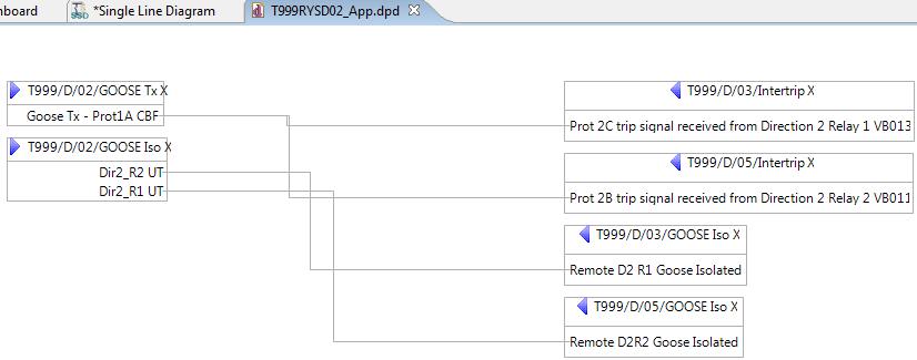
Fig. 9 Application Worksheet, Example of Mapping GOOSE Messaging
The exported .scd files can be imported into the specific vendor tools to build the .cid files.
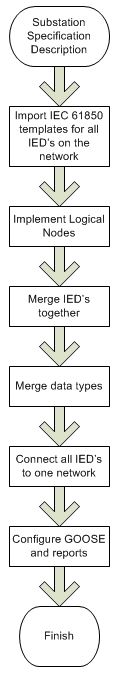
Fig. 10 Top Down Engineering Flow
Results
The major upside of this approach being that any standards based changes at the upper engineering levels in Helinks means there is a hassle free repeatable engineering process for recreating the IED files. For FAST to engineer CID files the following were supplied by the utility: the Single Line Diagram, required LN/Signals lists per bay type, a GOOSE matrix showing functional interactions, IP Addressing and commissioned CID files for the final comparison. FAST was successful at re-engineering an IEC 61850 Station Bus Substation Automation System with multi-vendor IED's using HELINKS STS. Our results have been presented with great interest from the utility.
HELINKS STS is an extremely powerful player in the IEC 61850 vendor independent template / library based engineering market. Offering simple palette based click and drag design to the complexities of integrated protection settings configuration.
References
HELINKS STS
Brenton Ford
SCADA Para Professional, FAST Engineering
Shaun Lumley
SCADA and Software Engineer, FAST Engineering
Wade Harris
Senior SCADA Engineer/Director, FAST Engineering
Contact Us About This Article